
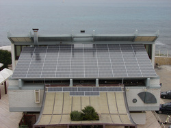
 We all think of sunshine when someone mentions the coast, and it's easy to think of PV as being ideally suited for life on the coast. After all, surely you're talking about the sunny South and there's not much to shade it except a few waves, right? This of course is generally true, and a PV system on the coast should be a success. But being on the coast does bring with it a number of challenges, namely sand, salt and the wind. These are of course problems that any structure needs to face, but that doesn't mean they can be ignored - indeed, since many installation crews work all over the UK, it's often completely forgotten. I've just put together a specification for a 250kWp array on a new industrial unit in Cornwall, and with this in mind, here are some of the design considerations I bore in mind: 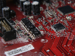 The air on the coast is much more salty than "usual" - we all know the smell of the sea - and this can accelerate electrolytic corrosion of metals. Any equipment installed on the coast should allow for this; ask for modules and inverters with salt mist test certification. The IP rating alone won't tell you this, as salt is a particularly corrosive substance that will get through seals over time. The photo on the left shows the power circuit board of a Fronius inverter that has been through this test. This particular manufacturer has lacquered the circuitry so despite a relatively low IP rating, components will still function if salt gets in. Other products may rely on a hermetic seal... But will that seal last 25 years? Make sure it's been tested! 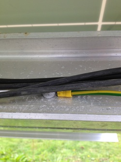 The rest of the structure can be affected too. The array mounting structure will be exposed to the hostile environment so choosing materials carefully - and avoiding electrically dissimilar metals - is a definite action point. Untreated steel will probably rust, whereas alumninium and stainless steel should last longer. Using an inverter without a transformer will, by design, result in a leakage current to true earth. As can be seen in the attached photo, this leakage will affect even inland systems and you'll get accelerated corrosion (the system is less than a year old but there's a distinct patch of oxidation visible already and the copper fitting is already "rusting"). As seen in the photo, inland this is normally within accetable limits, but when on the coast there's already an increased risk so consider including a transformer for galvanic isolation to minimise this effect. This also applies to other exposed metalwork, such as cable mounting systems (choose stainles steel or coated) and the building itself. Even if the PV components are tough enough, will it affect more delicate cladding and finishes? On top of all the salt in the air, you've got to contend with sand too. The array itself should be fine as long as it's at a sufficient angle to prevent sand piling up. On the other hand, sand, as with any other fine particle, does have a habit of clogging filters and fans. Again, this is where quality equipment comes into play: High end manufacturers such as SMA and Fronius separate the cooling air channel from the components themselves. However, the fans pulling this air through can still get blocked and/or be abraded by the sand, so consider where the inverters are to be kept, and whether an additional filter would help. Finally, there's the stronger wind that you normally get on coastal sites. While this is rarely a problem - at least in the UK where it's relatively docile - it should be accounted for in the fixing design. This is a factor included in designs in accordance with the MCS code MIS3002 and the Eurocode range (BS EN 1991), and should be done by your installation company by default.  In summary, installing PV near the coast does have additional challenges. But none of these challenges are insurmountable, and a well designed installation will perform as well as any other in the UK - if not better.
(Thanks to SMA and Fronius for some of these images)
0 Comments
Cooper Energy Engineering has submitted its report as an expert advisor on PV systems, as part of a retrospective planning application for a 37kWp solar array in an AONB in East Sussex. CEE was engaged by the planning consultants Parker Dann representing the system owner, via a contract with Southern Solar, to survey the existing installation, and produce a report commenting on the suitability of the existing design and make recommendations for any improvements. Since the installation was sited within the High Weald Area of Outstanding Natural Beauty (AONB), the focus of the study was on mitigating the visual impact of the array on the wider area. Our report found that while the array was of a reasonable scale, design and location for a less sensitive site, a number of measures could have been taken including landscaping for screening and using screw-piles rather than concrete foundations. 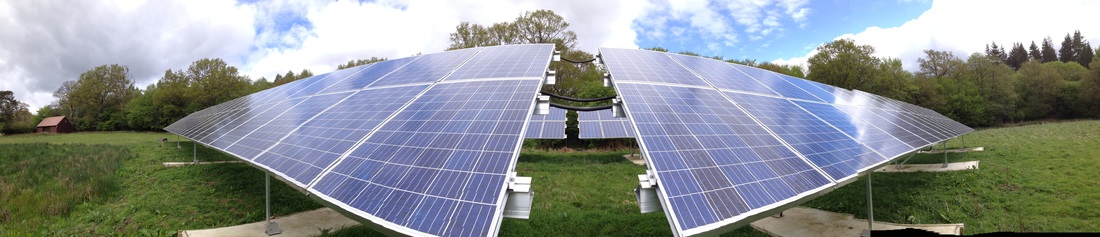
Cooper Energy Engineering is well placed to provide independent reports in support of Planning Applications. Obviously we do not recommend installing PV systems without first obtaining Planning Permission, or confirming that the system falls within the rules for permitted development. Further advice on Permitted Development rights and requirements for obtaining planning consent are given on the Planning Portal website, with separate criteria for domestic and non-domestic projects. If you would like project-specific advice, we would be happy to help - please contact us.
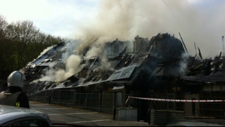 Fire safety of solar photovoltaic systems has been in the news again, this time because of a fire on a hotel near Dartmoor with a PV system. The fire wasn't caused by the array itself, but its presence meant that firefighters were hesitant to tackle the blaze before it had caused severe damage to the building. Thankfully, no-one was even hurt. When designed and installed correctly PV systems are safe and a well-trained firecrew can deal with them. But, because they are relatively new to the UK, every time this comes up, people understandably question the safety of PV. Fighting Fires involving PV  Firefighters are understandably wary of PV systems: By design, most installations will involve higher-than-normal voltage, DC circuits that are always live even when the mains is cut. However, a properly designed system will allow for that and minimise the exposure to the hazard. Furthermore, with proper training and equipment, the additional risk to firefighters tackling a blaze is actually minimal. However, one of the "issues" is that PV is so safe and fires happen so rarely that most crews don't have any experience in dealing with them! In fact, studies in the US and Germany have been carried out and have shown that if appropriate care is taken, the presence of a PV system should not affect whether a crew can tackle a blaze. Just earlier this month, the MCS held a conference specifically to address firefighters' concerns. It follows years of industry working with fire and rescue services (some of which I've been involved in). The aim of this particular conference was to bring those crews who had experienced PV fires together, so that lessons could be learned, procedures built on and crews trained appropriately. It also gave the industry a chance to communicate recent improvements in design: MCS scheme requirements also have recently changed to incorporate a number of ideas to help firefighters into designs and installations, such as fitting labels by the incoming fuse cut-out to signal that solar PV is on the roof. Minimising Risk by Design Obviously, as with any electrical system good workmanship, adherence to standards and using quality products will go a long way to providing a safe, reliable installation. But there are other best-practice details which are well worth bearing in mind for your project. A lot of it comes down to care and experience, but points include:
A lot of this comes down to taking time and care to do the job properly at both the design and installation stages, and then communicating the design with anyone that needs to know, such as fire crews and facility maintenance teams. Whether or not you think solar is an expensive energy source, there is no excuse for a rushed or cheap job.
There are many changes to the Guide, which is now maintained by MCS, and far too many to list here in detail. However, this is a flavour of the scope and scale of the updates:
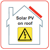 The new Fire & Rescue PV Notification sign In general, these changes are welcome, and will help to further raise the standard of installations around the country. There are also a number of references to the soon-to-be-enforced MCS standards for roof mounting products, which I will write about in another post. What is the Guide to the Installation of PV Systems? The Guide has been used in the UK PV industry for a decade, and is the primary set of rules and guidance on the design and installation of PV systems (way beyond the BS7671 Wiring Regulations, for example). The first two editions were published by the Department of Trade and Industry, and it is still often referred to - especially by old-timers - as the DTI Guide. Ever since its first edition, the guide has provided essential guidance to designers. It covers everything from selecting modules and inverters, safety factors for selecting DC cables and switchgear, AC wiring requirements (earlier editions of BS7671 didn't cover SSEGs) and safe installation methods. A copy of the latest version can be downloaded from the MCS website.
After several months of consultations with OFGEM, DNOs and stakeholders from the disitributed generation industry (of which I was a part), the Energy Networks Association published the latest update of Engineering Recommendation G83/2, replacing G83/1-1. The ENA has also published a revised version 19 of the Grid Code, which gives installers and manufacturers until 1st March 2014 to implement the necessary changes. Key Changes There have been a number of substantial changes to the Recommendation, which for the most part reflect the increasing penetration of renewable energy into the Grid. Key changes are:
The last point brings the document in line with the requirements for larger projects, and is to be widely welcomed as it brings greater stability to the public supply network. It's not quite the dynamic approach taken by Germany's current VDE-AR-N 4105 and others, but it is definitiely an improvement. The changes to multiple-site projects was the subject of considerable discussion in the Distributed Generation Working Group run by ENA for the purpose. The intention is to protect DNOs fairly against incremental changes to their network caused by rapid uptake of domestic PV systems. After all, 25 typical domestic PV systems - just one street - can create a 100kW generator on the network overnight without the DNO finding out about it until 28 days after the event. Yet doing the same as a single commercial project would require advance notice to allow for grid studies, reinforcement work etc. The challenge has been how to give DNOs fair notice without unduly interfering with customers getting a system installed. What is ER G83? Officially titled "Recommendations for the Connection of Type Tested Small-Scale Embedded Generators (Up to 16A per phase) in Parallel with Low Voltage Distribution Systems", Engineering Recommendation G83 is enshrined in the Grid Code for the UK. This Code is a set of requirements coordinating the efforts of the various Distribution Network Operators around the UK - the organistations that own the national electrical cabling system. G83 itself sets out the rules for connecting most domestic renewable energy systems to the public grid. It sets out the required installation and product standards, protection arrangements and the process by which potential clients can, via their consultants, apply for their system to be connected. A core part of G83 is the provision of protection against deviations in voltage and frequency, and providing systems to enhance the stability of the national power networks. A common misconception is that this is protecting the generator; actually it is the network that is being protected, and this is why network operators insist on implementing it before they let a system be connected. To illustrate this, many clients ask me "Why can't my system keep working when the mains fails?" The answer is quite simple: If the mains fails, it's because there's a fault or its been switched off, and either way there will be someone coming along to work on it soon. If it continued to generate, it would feed power into the fault, which would of course be rather dangerous for the linesman fixing the supply!
|
News
Industry news and comment, as well as company announcements, by James, our Company Director Archives
September 2021
Categories |
 RSS Feed

Copyright © 2020. Cooper Energy Engineering Ltd is UK registered company, no. 8253361. VAT registration no. 161 4825 15.
Registered address: Oundle Wharf, Station Road, Oundle, Peterborough PE8 4DE
Registered address: Oundle Wharf, Station Road, Oundle, Peterborough PE8 4DE